Contact: Mr.Wang 13585000194 / 15861488616
 Web: www.wxkbjx.com
 Add: Yuanqiao Road, Yixing City
Product List
PRODUCT LIST-
CONTACT US
- Contact: Mr.Wang
- Mobile: 13585000194
- Mobile: 15861488616
- Tel: 0510-85388408
- Fax: 0510-85388408
- Web: www.wxkbjx.com
- E-mail: sales@wxkbjx.com
- 502492439@qq.com
- Add: 42 Yuanqiao Road, Yixing
- Economic Development
- Zone, Wuxi City
Alloy cutting head and holder
Position:Home > Alloy cutting head and holder >
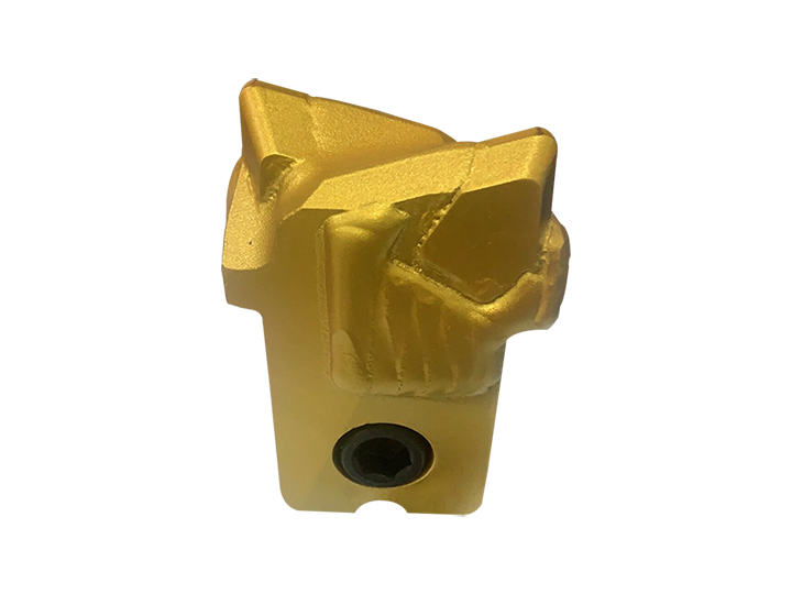
Reinforced alloy cutting tool 50
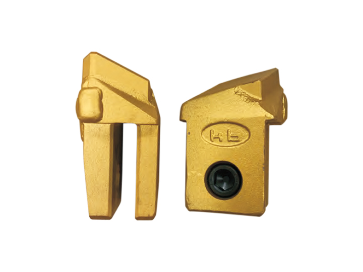
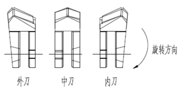
The shape and type of the blade
The cutting head used in the construction of a full casing rotary drilling rig can be divided into outer cutting (teeth), middle cutting (teeth), and inner cutting (teeth) according to their shape.
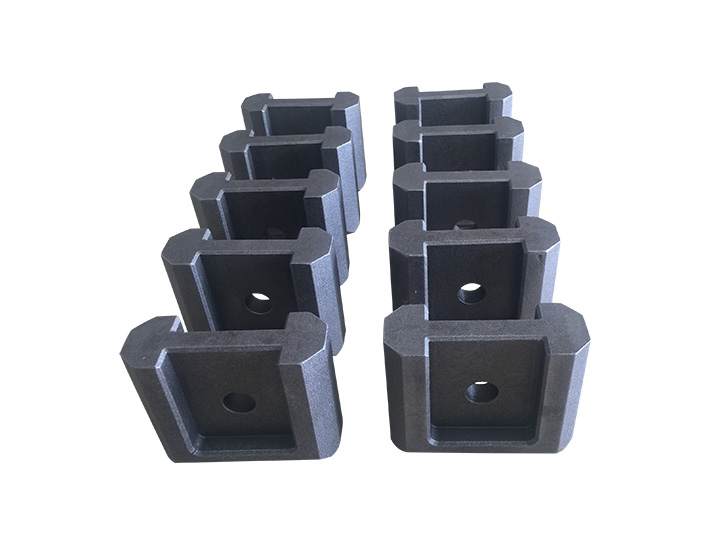
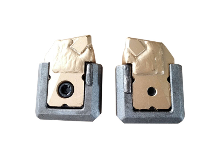
Installation of blade head
1) The number and arrangement of blade heads should be adjusted appropriately according to the geological conditions of the construction site. The distance between each blade should be controlled within the range of 180-220mm. Generally, the number of blade heads can be selected according to Table 1.
Table 1: Number of cutting heads for different diameter casings
2) The number and arrangement of different external teeth, middle teeth, and inner teeth have different cutting effects and efficiency. Adjusting the number and arrangement of external teeth, middle teeth, and inner teeth according to the geological conditions of the construction site can improve drilling efficiency. The arrangement of blade heads mainly has the following modes.
Mode A:
For ordinary formations, underground obstacles, smaller diameter boulders, block rock formations, etc., the standard arrangement of external teeth, internal teeth, external teeth, and internal teeth circulation can meet the construction requirements.
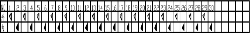 模式A刀头排列数量
模式B:
针对有中风化岩层、和套管直径接近的较大的块石、漂石等地层,一般应采用外齿、外齿、中齿、内齿、外齿、内齿的刀头安装方式。
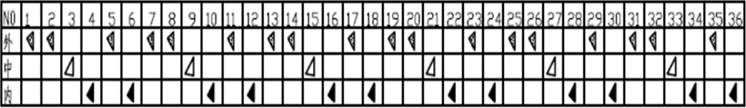 模式B刀头排列数量
Mode C:
When it is necessary to embed high strength and difficult to cut rock layers (such as requiring the cooperation of impact hammers and rolling cutters for construction), a cyclic arrangement of external teeth, external teeth, middle teeth, internal teeth, external teeth, external teeth, and internal teeth can generally be used for the installation of the cutting head.
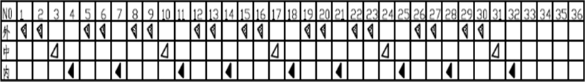 Number of blade arrangements in Mode C
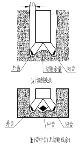
When cutting soft and medium hard rock layers, the rock is stripped or destroyed or crushed in the texture area (cracks or gaps between rock layers) due to cutting resistance, so there is basically no accumulation in the drilling ditch. However, large and hard rocks or hard rock layers that exceed the diameter of the casing have few textures and are difficult to break, resulting in cutting grooves along the trajectory of the blade. In this state, cutting residues will be generated between the inner and outer edges, increasing drilling resistance. Installing middle teeth can eliminate cutting residues and improve drilling and cutting efficiency.
In the process of cutting bedrock, it is necessary to scientifically arrange the blades to smoothly discharge debris, and to ensure that the blade protrudes about 10mm from the side of the casing inward and outward, to ensure sufficient clearance between the side of the casing and the hole wall, and to reduce surface friction. But if the protrusion is too large, it will lead to excessive blade load and affect the service life of the blade.
The cutting head used in the construction of a full casing rotary drilling rig can be divided into outer cutting (teeth), middle cutting (teeth), and inner cutting (teeth) according to their shape.
 |
 |
1) The number and arrangement of blade heads should be adjusted appropriately according to the geological conditions of the construction site. The distance between each blade should be controlled within the range of 180-220mm. Generally, the number of blade heads can be selected according to Table 1.
Table 1: Number of cutting heads for different diameter casings
| Nominal diameter of casing(mm) | Φ1000 | Φ1200 | Φ1500 | Φ2000 | Φ2500 | Φ3000 |
| Number of blade heads (pieces) | 16 | 18 | 24 | 30 | 40 | 48 |
Mode A:
For ordinary formations, underground obstacles, smaller diameter boulders, block rock formations, etc., the standard arrangement of external teeth, internal teeth, external teeth, and internal teeth circulation can meet the construction requirements.
|
套管公称直径 (mm) |
刀头数量(把) | |||
| 外齿 | 中齿 | 内齿 | 合计 | |
| Φ1000 | 8 | 0 | 8 | 16 |
| Φ1200 | 9 | 0 | 9 | 18 |
| Φ1500 | 12 | 0 | 12 | 24 |
| Φ2000 | 15 | 0 | 15 | 30 |
| Φ2500 | 20 | 0 | 20 | 40 |
| Φ3000 | 24 | 0 | 24 | 48 |
针对有中风化岩层、和套管直径接近的较大的块石、漂石等地层,一般应采用外齿、外齿、中齿、内齿、外齿、内齿的刀头安装方式。
|
Nominal diameter of casing (mm) |
Number of blade heads (pieces) | |||
| 外齿 | 中齿 | 内齿 | 合计 | |
| Φ1000 | 8 | 3 | 5 | 16 |
| Φ1200 | 9 | 3 | 6 | 18 |
| Φ1500 | 12 | 4 | 8 | 24 |
| Φ2000 | 16 | 5 | 11 | 32 |
| Φ2500 | 20 | 7 | 13 | 40 |
| Φ3000 | 24 | 8 | 16 | 48 |
When it is necessary to embed high strength and difficult to cut rock layers (such as requiring the cooperation of impact hammers and rolling cutters for construction), a cyclic arrangement of external teeth, external teeth, middle teeth, internal teeth, external teeth, external teeth, and internal teeth can generally be used for the installation of the cutting head.
|
套管公称直径 (mm) |
刀头数量(把) | |||
| 外齿 | 中齿 | 内齿 | 合计 | |
| Φ1000 | 9 | 3 | 4 | 16 |
| Φ1200 | 10 | 3 | 5 | 18 |
| Φ1500 | 14 | 3 | 7 | 24 |
| Φ2000 | 18 | 5 | 9 | 32 |
| Φ2500 | 22 | 7 | 11 | 40 |
| Φ3000 | 26 | 9 | 13 | 48 |
In the process of cutting bedrock, it is necessary to scientifically arrange the blades to smoothly discharge debris, and to ensure that the blade protrudes about 10mm from the side of the casing inward and outward, to ensure sufficient clearance between the side of the casing and the hole wall, and to reduce surface friction. But if the protrusion is too large, it will lead to excessive blade load and affect the service life of the blade.
Prev:Cutting 45